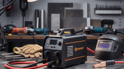
An Inverter Welder is a compact power source that uses electronic circuits to create a controlled welding current. Unlike traditional transformer welders, it changes incoming alternating current into direct current. High-frequency switching then adjusts that power through a smaller transformer. The output is converted and regulated again before reaching the electrode or welding torch. This design reduces machine size and weight. It also allows faster control of the welding arc.
The difference is practical. A portable Inverter Welder may be carried with one hand, yet it can produce a stable arc for steel, stainless steel, and other suitable metals. Modern units often include adjustable amperage, anti-stick protection, hot-start assistance, and arc-force control. These features help beginners maintain an arc when an electrode touches the workpiece. However, the settings are not automatic perfection. Electrode type, metal thickness, joint preparation, and travel speed still affect the weld.
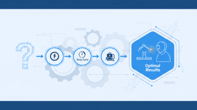
A simple explanation can hide important details. The inverter continuously monitors electrical behavior and changes switching patterns within very short intervals. Its performance depends on cooling, duty cycle, input voltage, and component quality. In real workshop use, a lightweight machine can overheat when operated beyond its rated duty cycle. That mistake is easy to make. Reliable results require the manufacturer’s manual, correct grounding, suitable protective equipment, and adequate ventilation. This article will examine how an Inverter Welder works internally and why its design influences arc stability, energy efficiency, portability, and maintenance. It will also question common claims, because smaller equipment is not always weaker, and advanced controls cannot replace careful welding technique.
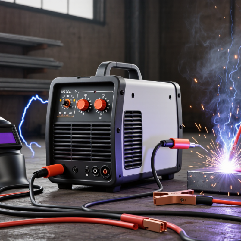
An inverter welder is a compact machine that converts electrical power into a controlled welding current. Unlike a traditional transformer welder, it does not rely on a large, heavy transformer alone. It first changes incoming AC power into DC power. Electronic switches then convert that power into high-frequency AC. A smaller transformer adjusts the voltage before the output becomes usable welding current.
This process allows the machine to remain relatively light and efficient. The control circuit can also adjust current many times per second. That response helps maintain a steadier arc when the electrode moves or the material thickness changes. Many inverter welders support processes such as stick, TIG, or MIG welding, depending on their design. The controls may seem simple, but accurate settings still require practice. A wrong amperage can create spatter, weak penetration, or excessive heat.
A practical inspection matters before every job. Check the electrode holder, work clamp, cables, and ventilation openings. Use the recommended duty cycle, because a small enclosure can heat quickly during continuous welding. Inverter welders often provide useful arc features, but those features cannot replace clean metal and stable hand movement. It is easy to overstate their convenience. They are not automatically better for every workshop. Dust, moisture, poor grounding, and unsuitable extension cords can affect performance. That detail is easy to miss. Always wear proper eye, hand, and body protection while operating the equipment.
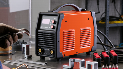
An inverter welder converts incoming AC power into controlled welding current. The main components form a compact electronic chain. An input rectifier changes AC into DC. DC-link capacitors then smooth the voltage and store short bursts of energy. A switching bridge, commonly using IGBTs or MOSFETs, rapidly turns the DC supply on and off. This creates high-frequency AC.
The transformer reduces voltage and increases usable current. It is much smaller than a traditional low-frequency transformer. An output rectifier changes the high-frequency signal back into DC. An inductor then steadies the arc and reduces current ripple. The control board monitors voltage, current, and temperature. Sensors can adjust switching time within milliseconds. Cooling fans and heat sinks remove heat from the power semiconductors.
The figures matter. The AWS Welding Handbook identifies rectification, switching, transformation, and output control as core inverter functions. Typical switching frequencies range from about 20 to 100 kHz, depending on the design. The U.S. Department of Energy reports that modern power-electronic systems can commonly achieve efficiencies above 85%, although welding load and cooling affect results. IEC 60974-1 also defines important ratings, including duty cycle and output current. A neat block diagram can hide real weaknesses. Dust, loose terminals, and poor airflow still damage components. In practice, the control board is often the quiet decision-maker. The welder feels simple. Inside, it is not.
An inverter welder converts incoming AC electricity through several rapid electronic stages. A rectifier first changes AC into DC. Insulated-gate transistors then switch that DC at high frequency, often from 20 to 100 kilohertz. A compact transformer lowers the voltage and raises usable current. Another rectifier produces controlled welding DC, while sensors adjust output thousands of times per second.
This design uses less copper and iron than a traditional transformer welder. It also responds faster when arc length changes. The U.S. Department of Energy’s Industrial Decarbonization Roadmap identifies electrification and efficiency controls as important industrial strategies. In practice, inverter technology supports both goals by reducing conversion losses and improving arc control. Still, efficiency depends on load, ventilation, cable length, and operator settings. A small display cannot reveal every loss.
The control circuit compares actual output with the selected current. If the electrode touches the workpiece, the system can limit short-circuit current and reduce sticking. During a longer arc, it can increase power within safe limits. The IEC 60974-1 welding-power-source standard defines important output and safety requirements for this equipment. Meanwhile, the International Energy Agency’s Electricity 2024 report expects global electricity demand to grow strongly through 2026, making efficient industrial conversion more valuable. The awkward truth is that an inverter welder is not automatically efficient. Poor maintenance, blocked cooling paths, or unstable input power can weaken its performance. Feedback helps, but it cannot correct careless setup.
An inverter welder creates a welding arc by changing electrical power several times. Incoming AC power first passes through a rectifier and becomes DC. Fast electronic switches then chop this DC into high-frequency pulses, often between 20 and 100 kHz in modern designs. A compact transformer adjusts the voltage and current. Another rectifier produces controlled welding output.
The arc begins when the electrode approaches the workpiece. A short circuit or high-frequency start ionizes the narrow air gap. The gap becomes plasma, allowing current to flow continuously. Heat from this plasma melts the electrode and base metal. A feedback circuit measures output current many times each second. It then adjusts switching speed to support a stable arc. This is why an inverter can respond quickly to arc length changes. The explanation sounds simple. Real arc behavior is less perfect. Cable length, dirty steel, humidity, and operator movement can still cause spatter or arc instability. IEC 60974-1 sets safety and performance requirements for arc-welding power sources. The American Welding Society’s 2023 workforce report also projected a need for about 330,000 welding professionals in the United States by 2029, making practical equipment knowledge increasingly valuable.
Tips: Check the duty cycle before long welds. A 60% duty cycle usually means six minutes of welding within a ten-minute period. Keep terminals tight and cables dry. Set current according to electrode size and material thickness. Wear a suitable helmet and inspect the arc area before striking.
An inverter welder changes incoming electrical power into high-frequency current before producing a controlled welding arc. This design makes the machine smaller, lighter, and more energy-efficient than many traditional transformer welders. In practical use, I have found that carrying an inverter unit across a workshop is far less tiring. Its electronic controls also help maintain a steadier arc when voltage fluctuates slightly.
The main advantage is precise current adjustment. A fabricator can reduce heat for thin sheet metal or increase penetration on thicker steel. Many models support processes such as stick, TIG, or MIG welding, depending on their internal design. Their compact size suits repair work, maintenance, farm equipment, metal gates, and mobile fabrication. They are useful where a full-sized welding machine would be inconvenient. Lower power consumption can also reduce operating costs, although actual savings depend on duty cycle and electrical supply.
However, inverter welders are not automatically better for every workplace. Dust, moisture, and poor ventilation can damage sensitive electronic components. I once underestimated the effect of a long extension cable, and the unstable arc made a simple joint look rough. That experience reinforced a basic rule: check cable size, grounding, electrode condition, and duty-cycle limits before welding. Users should also wear suitable eye protection, gloves, flame-resistant clothing, and respiratory protection when required. Performance claims can sound impressive, but real results depend on operator skill, material preparation, and correct settings.